Views: 0 Author: Site Editor Publish Time: 2026-09-07 Origin: Site
Trapped air in diesel fuel lines acts as a physical blockage. It represents the most common cause of generator failure-to-start and rough idling conditions. Facility managers and operators face critical power downtime when a generator runs dry. Routine filter maintenance or line leaks also introduce air into the closed loop. You need an immediate and correct air-purging procedure to restore standby power.
Executing a systematic bleeding procedure prevents catastrophic damage to high-pressure fuel injectors and injection pumps. Diesel fuel provides essential lubrication to these tight-tolerance components. Running the system dry causes rapid metal-on-metal wear. This guide details the exact mechanical and electronic protocols required to bleed diesel generator fuel system architectures. You will learn how to evaluate component integrity and determine when replacement parts are necessary.
Identify the Intrusion Source: Bleeding is ineffective if the root cause of air intrusion (e.g., degraded O-rings, cracked lines, or empty tanks) is not resolved first.
System-Specific Protocols: Mechanical injection systems require manual priming and cracking of bleed screws, whereas modern electronic systems often utilize self-priming lift pumps activated by cycling the ignition.
Component Protection: Running a diesel engine with air in the lines eliminates the lubricating properties of diesel fuel, risking immediate scoring and failure of the injection pump.
Diagnostic Value: The bleeding process serves as a diagnostic baseline to evaluate the condition of critical Engine & Parts, including lift pumps, banjo bolts, and fuel filters.
Table of Contents
Air intrusion disrupts the precise hydraulic pressure required for diesel combustion. The fuel system operates under a continuous vacuum from the tank to the lift pump. Any breach in this low-pressure side draws air directly into the fluid stream. Understanding the exact entry point dictates your repair strategy. You cannot permanently fix a vapor lock without identifying how the air bypassed the sealed system.
Maintenance-induced air represents the most frequent cause of system aeration. Technicians introduce air during the routine replacement of primary water separators and secondary fuel filters. Removing a filter housing exposes the fuel galleries to the atmosphere. Failing to pre-fill the new filters forces the lift pump to push a massive volume of air through the lines. This air compresses inside the injection pump, preventing the hydraulic pressure needed to pop the injectors open.
Fuel starvation occurs when the generator tank runs completely dry. The pickup tube draws pure air from the bottom of the tank. This air travels through the entire fuel architecture. It fills the lift pump, filter housings, and the high-pressure injection pump. Recovering from a dry tank requires a comprehensive, full-system bleeding procedure. Simply adding fuel to the tank will not resolve the vapor lock. The mechanical pump cannot pull liquid fuel if the lines are full of compressible air.
Component degradation creates microscopic entry points for air. Aging rubber fuel lines become brittle and develop hairline cracks. Constant engine vibration loosens hose clamps over time. Degraded O-rings inside quick-disconnect fittings lose their sealing capacity. These micro-leaks often allow air to enter without leaking visible liquid fuel. Because the supply side operates under a vacuum, the system sucks air inward rather than pushing fuel outward. This makes visual diagnosis incredibly difficult.
A successful bleed yields specific operational results. You must verify these conditions before returning the generator to standby status:
The engine turns over and fires immediately upon cranking.
RPMs remain stable at 1800 (for 60Hz systems) when the transfer switch applies a facility load.
The generator exhibits zero hesitation or surging during sudden load step changes.
The exhaust stack shows no white smoke, which would indicate unburnt fuel and poor injection timing caused by aeration.
Attempting a fuel system bleed without the correct tools guarantees frustration and damaged components. Brass bleed screws and injector nuts are highly susceptible to rounding. Using adjustable wrenches or locking pliers destroys these fittings. Proper preparation ensures a clean, efficient, and safe maintenance evolution on the generator skid.
You must source properly sized metric and SAE flare nut wrenches, also known as line wrenches. Line wrenches grip multiple sides of the hex nut. This prevents rounding off the soft metal fittings found on high-pressure injection lines. A standard 3/8-inch drive socket set handles filter housing bolts and mounting brackets. Flathead screwdrivers assist in gently prying stubborn hose connections or operating specific manual primer levers found on older mechanical lift pumps.
Consumables play a major role in contamination control. Keep a dedicated supply of clean diesel fuel in a sealed container for manual priming and filter pre-filling. Heavy-duty, lint-free shop rags absorb inevitable spills around the bleed screws. Never use standard paper towels, as they leave behind microscopic fibers that will clog injector nozzles. Place a dedicated fuel catch pan beneath the engine block to capture purged fuel. Always wear safety glasses. High-pressure fuel spray can penetrate the skin and cause severe injury.
Procure the necessary replacement components before starting the procedure. Install OEM-specified fuel filters to guarantee correct micron ratings and flow rates. Keep a supply of new copper crush washers for the banjo bolts. Reusing old, work-hardened crush washers guarantees a future air leak. Inspect and replace the O-rings for the filter housings if they appear flattened or cracked. Using high-quality Engine & Parts ensures the system holds prime after the repair and withstands the intense vibration of a running diesel engine.
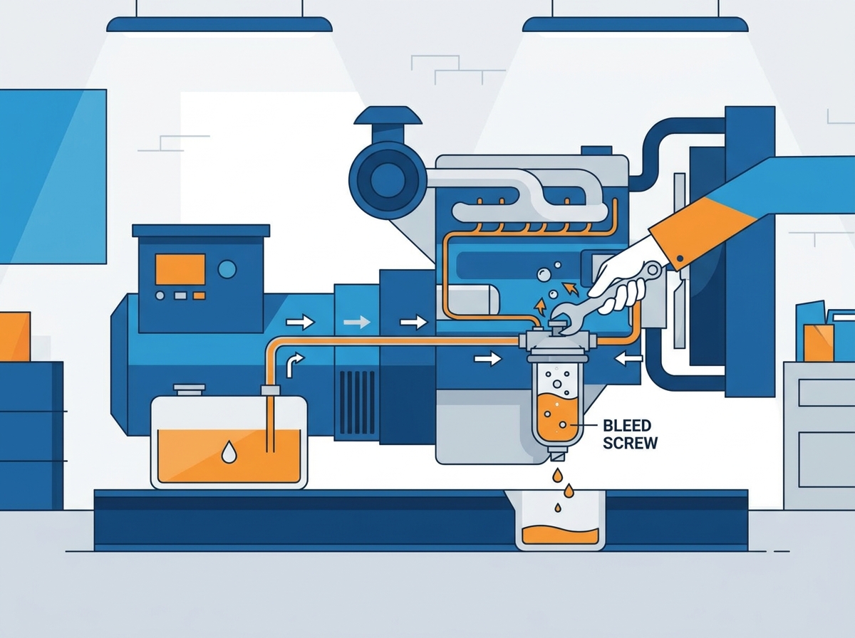
Safety and sequence dictate the success of the bleeding process. Engage the generator's emergency stop (E-stop) button immediately. Disconnect the negative terminal of the starting battery. This ensures zero accidental cranking while your hands are near rotating belts or high-pressure lines. Close the main fuel supply valve located at the base of the day tank or main storage tank to prevent gravity siphoning.
Clean the exterior of the filter housings thoroughly. Use a heavy-duty engine degreaser and a stiff nylon brush. Dirt and particulate matter resting on the housing can easily fall into the open fuel lines when you remove the filter. Even microscopic debris will permanently score the high-pressure injection pump or clog the injector nozzles, leading to a complete engine rebuild.
Map the exact bleed sequence before turning a wrench. You must always bleed from the lowest pressure point to the highest. Deviating from this path pushes trapped air deeper into the system. Follow this exact progression:
Primary Filter (Water Separator)
Secondary Fuel Filter
Inlet of the Injection Pump
High-Pressure Injector Lines (Only if the engine fails to start after bleeding the low-pressure side)
Remove the old filters using a strap wrench or the appropriate socket for cartridge-style housings. Inspect the bottom of the housings for heavy debris, rust flakes, or excessive water separation. Disconnect the Water in Fuel (WIF) sensor wiring harness carefully. Set the sensor aside in a clean location. Clean the mating surface of the filter header with a lint-free rag to ensure a perfect seal.
Pre-fill the new filter elements with clean diesel fuel. Pour the fuel slowly into the outer ring of the filter, not the center hole. The outer ring feeds the dirty side of the filter media. Pouring into the center hole bypasses the filter media entirely and sends unfiltered fuel directly to the injection pump. Pre-filling minimizes the total volume of air introduced into the system, drastically reducing the time required to manually pump the primer.
Lubricate the new filter gaskets with a light coat of clean engine oil or fresh diesel fuel. Dry gaskets bunch up, roll out of their grooves, and tear during installation. Install the new filters hand-tight. Do not use a filter wrench to tighten them. Over-tightening distorts the housing and pinches the O-ring, creating an immediate vacuum leak. Reconnect the WIF sensor harness securely.
Open the main fuel supply valve from the tank. Locate the manual primer pump. Manufacturers typically mount this plunger, button, or diaphragm lever directly on the fuel filter housing or the mechanical lift pump on the side of the engine block. The primer draws fuel from the tank and pressurizes the low-pressure side of the system.
Pump the manual primer repeatedly. Initially, the plunger will feel very light and offer zero resistance. Continue pumping until you feel distinct physical resistance. This stiffening indicates that liquid fuel has displaced the air inside the filter housings and lines. If the lever feels completely dead and offers no stroke, the internal engine camshaft lobe is likely resting on the pump arm. Reconnect the battery and bump the engine starter for a fraction of a second to rotate the engine and free the pump arm.
Locate the primary bleed screw. This is typically a small 10mm or 12mm bolt with a hex head, or a banjo bolt situated at the highest point of the fuel filter housing. Alternatively, look for a specific bleed valve at the inlet of the injection pump. Place your catch pan directly below this area and wrap a shop rag around the base of the fitting to control the spray.
Open the bleed screw 1 to 1.5 turns using your line wrench. Do not remove the screw completely. Continue operating the manual primer pump with your other hand. Watch the fluid escaping from the base of the bleed screw. You will see a mixture of fuel and air bubbles. The fuel will sputter, foam, and hiss as the trapped air escapes under pressure.
Keep pumping until a solid, bubble-free stream of clear fuel flows from the screw threads. Aerated fuel looks milky or cloudy. Wait until the fluid runs completely clear. The moment the stream runs clear, tighten the bleed screw immediately. Maintain downward pressure on the primer pump while tightening. This positive pressure prevents ambient air from being sucked back into the open threads.
If the engine fails to start after bleeding the low-pressure side, air has bypassed the injection pump. You must now bleed the high-pressure injector lines. Locate the steel fuel lines connecting the injection pump to the individual engine cylinders. Loosen the fuel line nuts at the injectors. Crack them open roughly half a turn using a line wrench.
Reconnect the starting battery and release the E-stop. Crank the engine in short 10 to 15-second bursts. Watch the loosened injector fittings. Fuel will begin to weep from the threads. Continue cranking until the weeping fuel shows absolutely no bubbles. Tighten the injector nuts to the manufacturer's exact torque specification.
Warning: Observe strict starter motor limits. Allow the starter to cool for a full 60 seconds between cranks. Continuous cranking overheats the starter motor windings and drains the battery rapidly. It also risks burning out the intake air heaters or glow plugs. Patience prevents secondary component failures.
Clear all spilled fuel from the engine block. Remove the catch pans and dispose of the purged fuel according to environmental regulations. Wipe down all fittings with a dry rag. This allows you to easily spot fresh leaks during the test run. A clean engine block is essential for accurate visual inspections.
Start the generator. The engine may run rough or hunt for idle speed for the first few seconds. Residual micro-bubbles passing through the injector return lines cause this temporary instability. The idle should smooth out entirely within one minute. If the engine continues to surge, air remains trapped in the governor housing or injection pump.
Apply a facility load or connect a load bank. Run the generator at a minimum of 30% capacity. Idling a diesel engine does not generate enough fuel pressure to clear stubborn air pockets, and it leads to wet stacking. Running under load forces the fuel system to operate at maximum pressure and flow rate. This ensures all remaining air purges back to the tank via the return lines.
Generator fuel systems utilize either mechanical or electronic priming mechanisms. Understanding the differences dictates your troubleshooting approach. Each system presents distinct operational advantages and specific failure modes during the bleeding process.
Evaluation Dimension | Self-Priming Electronic Systems | Mechanical Injection Systems |
|---|---|---|
Priming Method | Electric lift pump activated by ECU/Ignition. | Manual hand plunger or diaphragm lever. |
Labor Intensity | Low. Requires cycling the control panel switch. | High. Requires physical pumping and wrenching. |
Component Dependency | Relies on battery voltage, relays, and electric pump health. | Relies on camshaft rotation, manual seals, and physical effort. |
Field Serviceability | Difficult. Pump failure requires electrical diagnostics. | Excellent. Fully mechanical and easily bypassed or repaired. |
Air Purge Route | Automatically pushes air through the return line to the tank. | Requires manual venting to the atmosphere via bleed screws. |
Modern diesel generators feature common-rail injection and electronic control units (ECUs). These systems utilize electric lift pumps to pressurize the fuel lines. The bleeding procedure requires significantly less manual labor. Turn the control panel key or switch to the "ON" position without engaging the starter motor.
This action activates the electric lift pump for a predetermined cycle, usually 30 to 60 seconds. You will hear the pump humming near the frame rail or fuel tank. Cycle the key 4 to 5 times. Leave the ignition on for 30 seconds during each cycle. The electric pump automatically pushes fuel through the filters, forcing trapped air back to the main tank via the fuel return line. This system heavily relies on strong battery voltage and intact pump relays. If the battery is weak, the pump will not generate enough pressure to overcome the check valves.
Legacy generators and heavy-duty industrial units rely on mechanical injection architectures. These systems utilize a mechanical lift pump driven directly by the engine camshaft. Bleeding these systems strictly requires manual intervention. Operators must physically crack the bleed screws and manually pump the primer lever.
Mechanical systems offer superior reliability in harsh environments. They do not depend on delicate electronic sensors, wiring harnesses, or electric motors. However, the trade-off involves intense manual labor. The process requires precise torque management on brass fittings. Over-tightening a banjo bolt will shear the hollow shaft, causing an immediate, massive fuel leak and rendering the generator inoperable until a replacement bolt is sourced.
Even with correct procedures, fuel systems can resist priming. Identifying the specific symptoms of a bleeding failure prevents wasted time. Operators must distinguish between a simple procedural error and a hard component failure requiring parts replacement.
Symptom | Root Cause | Field Mitigation Strategy |
|---|---|---|
Primer pump never gets stiff. | Massive vacuum leak on the suction side. | Inspect filter O-rings for pinching. Check hose clamps. |
Engine starts, runs 30s, then stalls. | Air pocket trapped in the injection pump. | Re-bleed the secondary filter and injection pump inlet. |
No fuel reaches the filter housing. | Clogged pickup tube or failed lift pump. | Blow compressed air back into the tank to clear the screen. |
Fuel leaks from banjo bolt after tightening. | Reused or scored copper crush washer. | Replace with brand new copper washers and re-torque. |
A manual primer that never gets stiff indicates a massive air leak. The pump is drawing ambient air instead of pulling heavy liquid fuel from the tank. Alternatively, the engine may start successfully, run for 30 seconds, and stall abruptly. This stalling confirms the system is sucking air under operational vacuum, draining the filter housing faster than the lift pump can fill it.
Inspect all newly installed gaskets immediately. A pinched filter O-ring is the most common culprit. Ensure the old O-ring was not left stuck to the filter header, causing a double-gasket situation. Verify that no copper crush washers were reused on the banjo bolts. Check the drain valve at the bottom of the water separator to ensure it is fully closed and not weeping fluid.
Sometimes no fuel reaches the filter housing despite rigorous manual pumping or electronic cycling. This points to a restriction in the supply side or a failed pump diaphragm. Verify the physical fuel level in the tank using a dipstick. Do not rely solely on the electronic fuel gauge, which may be stuck or reading inaccurately.
Check for blocked pickup tubes inside the tank. Algae growth, sludge, or ice can completely clog the intake screen. Test the lift pump for proper vacuum and pressure output. If the manual primer lever moves freely but moves no fluid, the internal check valves have likely shattered or the rubber diaphragm has torn. The pump requires immediate replacement.
Facility operators can handle basic fuel system maintenance. Field-level tasks include filter changes, manual bleeding procedures, replacing low-pressure rubber hoses, and swapping out damaged WIF sensors. These tasks require standard hand tools and basic mechanical comprehension of fluid dynamics.
Professional intervention becomes necessary when the high-pressure side fails. If the injection pump loses prime repeatedly despite a perfectly sealed low-pressure system, the internal pump shaft seals have failed. If injectors require removal, cleaning, and bench testing, call a certified diesel technician. Attempting to force-start a dry injection pump with starting fluid will cause catastrophic metal-on-metal wear. Always source OEM Engine & Parts to maintain factory pressure tolerances.
Inspect all previously cracked fittings for micro-leaks immediately after the generator reaches operating temperature and maximum fuel pressure.
Verify stable voltage and frequency output on the main control panel while the generator runs under a 30% minimum load to ensure the governor is responding correctly.
Document the bleed procedure in the facility maintenance log, noting any replaced gaskets, hoses, or filters to track component lifespan.
Stock a dedicated spill kit, line wrenches, and spare copper crush washers directly inside the generator enclosure for rapid emergency access during a power outage.
A: Failing to bleed the system will prevent the engine from starting. If it does start, trapped air will cause rough idling, stalling, and severe lack of lubrication in the injection pump, leading to costly mechanical failure.
A: The air is fully purged when the fuel exiting the bleed screw or injector line flows as a solid, continuous stream with absolutely no sputtering, foaming, or visible bubbles.
A: No. Using starting fluid (ether) in a modern diesel engine can cause severe engine damage, including bent connecting rods or shattered pistons, especially in engines equipped with intake air heaters or glow plugs.
A: A continuous loss of prime indicates an active air leak in the low-pressure side of the fuel system. Common causes include degraded fuel lines, loose hose clamps, cracked filter housings, or failing check valves in the lift pump.
A: Never crank the starter motor for more than 15 seconds at a time. Allow the starter to cool for at least 60 seconds between attempts to prevent overheating and burning out the starter motor.


 Energy Storage System