Views: 0 Author: Site Editor Publish Time: 2026-08-27 Origin: Site
Uninterrupted power is a baseline requirement for industrial, commercial, and critical-care facilities. It is not a luxury. When the grid fails, operations must continue without a single dropped cycle. Procuring backup or prime power without understanding the underlying mechanics often leads to chronic underloading, emissions compliance failures, or catastrophic failure during grid outages. Facility managers frequently install oversized units that glaze cylinders or undersized units that stall under heavy motor starting loads. Understanding exactly how a diesel generator set converts chemical energy into electrical power is the prerequisite for accurate sizing, technical evaluation, and long-term asset management. We will break down the thermodynamic and electromagnetic processes that make these machines work. You will learn how to evaluate transient load acceptance, navigate emissions regulations, and mitigate operational risks like wet stacking to ensure your facility remains powered under any condition.
A diesel generator set operates through a two-step conversion process: the internal combustion engine converts fuel into mechanical energy via compression ignition, and the alternator converts that mechanical energy into alternating current (AC) electrical power.
System performance is strictly dictated by the synergy between the engine's load acceptance capabilities and the alternator's electromagnetic induction efficiency.
Evaluating a unit requires balancing fuel efficiency, alternative fuel compatibility (like HVO), and capital cost against stringent emissions regulations (e.g., EPA Tier 4 compliance).
Operational risks, such as "wet stacking" from chronic underloading, must be mitigated through precise capacity planning and regular load bank testing.
Table of Contents
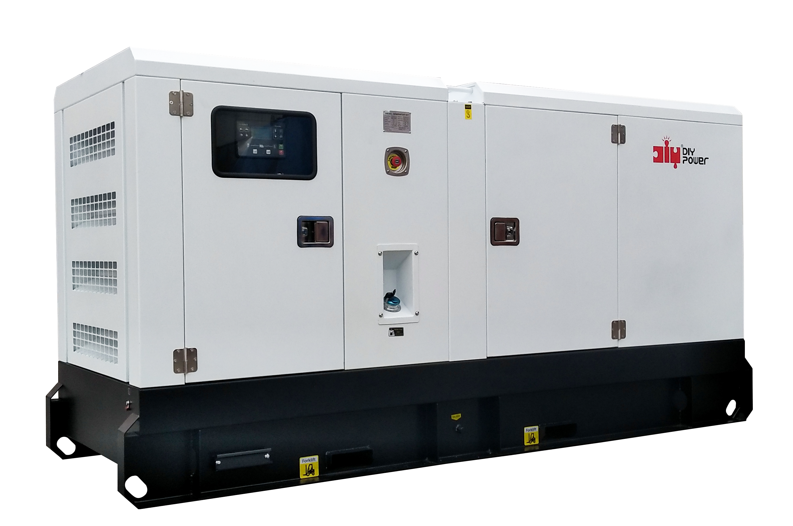
A generator set is the physical integration of a diesel internal combustion engine and an electrical alternator. Manufacturers mount these two primary components together on a single heavy-duty steel skid. This rigid base frame maintains strict alignment between the engine crankshaft and the alternator rotor. Heavy-duty neoprene or spring vibration isolators sit between the machinery and the skid. They prevent the violent mechanical forces of the running engine from transferring into the facility's concrete foundation.
You cannot deploy a generator effectively without understanding its operational classification. Manufacturers rate equipment based on the mechanical demands and thermal limits of the engine block and alternator windings. Deploying a unit outside its designated rating leads to rapid mechanical degradation and voided warranties.
Operational Classification | Mechanical Definition | Load Profile and Runtime Limits |
|---|---|---|
Standby Power | Emergency backup during utility grid failures. Components are sized for intermittent, short-duration thermal stress. | Variable loads for the duration of a power outage. Maximum of 200 to 500 hours per year. No sustained overload capability. |
Prime Power | Primary power source where utility power is unavailable. Built with heavy-duty cooling and filtration for continuous operation. | Variable loads for unlimited hours per year. Allows a 10% overload capability for one hour every twelve hours. |
Continuous Power | Steady-state base load power generation. Engineered for maximum thermal endurance without fluctuation. | Constant, non-varying 100% load for unlimited hours per year. No overload capability permitted. |
You must match the machine's rating to your site's load profile. If a facility requires continuous power for a remote mining site, utilizing a standby-rated machine will cause the engine to overheat and fail prematurely. The cooling systems and internal bearings of standby units simply cannot handle the thermal stress of continuous, unyielding operation.
Generating electricity from liquid fuel requires a precise, synchronized sequence of thermodynamic and electromagnetic events. This process occurs in three distinct phases.
The process begins inside the diesel engine through a thermodynamic cycle known as compression ignition. Unlike gasoline engines that use spark plugs, diesel engines rely entirely on extreme pressure and heat. The engine draws ambient air into its cylinders through an intake manifold and turbocharger. The pistons then travel upward, heavily compressing this air. This intense compression raises the air temperature to over 1,000 degrees Fahrenheit.
At the exact peak of compression, precision fuel injectors spray a fine mist of ultra-low sulfur diesel directly into the superheated cylinder. The fuel spontaneously ignites upon contact with the hot air. This ignition creates a rapid, controlled explosion. The expanding gases from this explosion force the piston back down with immense power. This downward stroke rotates the heavy steel crankshaft, converting the chemical energy of the fuel into raw mechanical energy.
The engine governor manages the fuel-to-load relationship. As the facility demands more electrical power, the physical resistance on the alternator increases. This magnetic resistance attempts to slow the engine down. The governor instantly detects this drop in speed and commands the fuel injectors to deliver more diesel. Increasing the fuel supply strengthens the combustion force, allowing the engine to maintain a stable rotational speed despite the heavier load. When the electrical load drops, the governor reduces the fuel supply to prevent the engine from overspeeding.
The mechanical energy from the rotating crankshaft transfers directly into the alternator. The alternator consists of two primary electromagnetic components: the rotor and the stator. The rotor connects directly to the engine crankshaft and spins at high speeds. The stator is a stationary steel ring lined with dense coils of copper wire, surrounding the rotor.
The conversion relies on the principle of electromagnetic induction. The spinning rotor acts as a powerful electromagnet, generating a moving magnetic field. As the rotor spins, this magnetic field constantly sweeps across the stationary copper windings of the stator. The movement of the magnetic field forces electrons within the copper wire to flow, inducing an alternating current (AC).
The frequency of this electrical output depends entirely on synchronous operation. The engine must maintain a precise, unwavering RPM to produce the correct electrical frequency for the facility. In North America, the standard frequency is 60 Hertz (Hz). To achieve this with a standard four-pole alternator, the diesel engine must spin at exactly 1,800 RPM. Any deviation in engine speed directly alters the electrical frequency, which will damage sensitive facility equipment.
While the engine governs frequency, the Automatic Voltage Regulator (AVR) governs the voltage. The AVR is a solid-state electronic component. It continuously monitors the output voltage leaving the alternator stator. Electrical loads constantly fluctuate in a facility. When large motors start, they pull massive amounts of inrush current, which causes the alternator's voltage to drop.
The AVR detects this voltage drop in milliseconds. It responds by increasing the direct current (DC) sent to the exciter field of the rotor. This intensifies the rotor's magnetic field, which in turn pushes the stator voltage back up to the target level. The AVR constantly adjusts this excitation current to maintain a stable, flat power supply, regardless of how aggressively the facility load fluctuates.
Power quality extends beyond just stable voltage. Facilities running sensitive electronics, telecommunications gear, or medical imaging equipment require clean power with low harmonic distortion. High-quality alternators utilize optimized winding pitches to eliminate harmful harmonic currents. This ensures the AC waveform remains a smooth sine wave, preventing overheating and erratic behavior in connected facility equipment.
A diesel generator set relies on several auxiliary subsystems to maintain operation. If any of these subsystems fail, the entire power generation process halts.
The fuel delivery system moves diesel from the storage tank to the combustion chambers. A primary lift pump draws fuel from the tank and pushes it through a series of water separators and micron filters. A high-pressure injection pump then pressurizes the clean fuel and distributes it to the individual cylinder injectors. Unused fuel routes back to the main tank through return lines, which also helps cool the injectors.
Evaluating fuel systems requires looking at long-term reliability, especially for standby applications. In standby setups, fuel often sits dormant in the belly tank for months. Diesel fuel degrades over time, absorbing water from condensation and breeding microbial growth. Facilities must implement integrated fuel polishing systems. These systems periodically circulate the fuel through heavy-duty filters and centrifuges to remove water and sludge. Proper tank sizing ensures you have enough runtime during an extended grid outage without allowing excess fuel to stagnate and spoil.
The lubrication system is the lifeblood of the diesel engine. An engine-driven gear pump forces oil through galleries to lubricate the crankshaft bearings, camshaft, and piston rings. This pressurized oil drastically reduces metal-on-metal friction. Oil also acts as a secondary cooling mechanism. It absorbs extreme heat from the underside of the pistons and carries it away to an oil cooler. Strict maintenance intervals for oil and filter changes are mandatory to prevent engine seizure.
The primary cooling system prevents thermal degradation during extended runtimes and heavy block loads. Diesel engines generate massive amounts of waste heat. A belt-driven water pump circulates a coolant mixture through passages in the engine block and cylinder heads. The coolant absorbs the combustion heat and flows into a large radiator. A massive cooling fan, driven by the engine, pulls ambient air through the radiator fins to extract the heat. Proper airflow into and out of the generator room or enclosure is required to keep this thermal loop functioning.
The exhaust system safely routes toxic, high-temperature combustion gases away from the engine room. The pathway includes heavy-duty steel piping, flexible bellows to absorb engine vibration, and industrial silencers to muffle the intense noise of the exhaust pulses. Modern diesel engines also utilize advanced aftertreatment systems to meet environmental regulations. These include Diesel Particulate Filters (DPF) to trap soot and Selective Catalytic Reduction (SCR) systems that inject urea to neutralize nitrogen oxides (NOx).
Commercial deployments almost always require acoustic and weather-protective enclosures. A raw diesel engine operating at full load produces deafening noise, often exceeding 100 decibels. Acoustic enclosures utilize sound-absorbing foam, baffled air intakes, and specialized exhaust routing to attenuate this noise, ensuring compliance with strict local noise ordinances. These heavy-gauge steel or aluminum enclosures protect the asset from rain, snow, and environmental degradation.
The digital control panel monitors engine telemetry and alternator output. It utilizes a microprocessor to continuously track oil pressure, coolant temperature, engine speed, battery voltage, and AC output metrics. If the control panel detects an abnormal condition—such as a sudden loss of oil pressure—it immediately executes an automatic shutdown sequence. This rapid intervention prevents catastrophic mechanical destruction.
In backup power applications, the generator control panel works in tandem with an Automatic Transfer Switch (ATS). The ATS sits between the utility grid, the generator, and the facility's electrical panel. It constantly monitors the incoming utility voltage. When a grid failure occurs, the ATS detects the voltage loss and sends a start signal to the generator control panel. Once the generator reaches 1800 RPM and the alternator builds 480V, the ATS mechanically breaks the connection to the dead utility grid and closes the connection to the generator. This mechanical handshake transfers the facility load safely to backup power.
Selecting the right equipment requires moving beyond basic kilowatt (kW) ratings. You must evaluate the mechanical capabilities of the system against the specific demands of your facility.
Transient load acceptance defines a generator's ability to handle sudden, large block loads without unacceptable voltage or frequency dips. When heavy equipment, such as industrial chillers, elevators, or HVAC motors, starts up, it draws a massive inrush of current. This sudden demand acts like a physical brake on the engine.
The mechanical robustness of the engine—its displacement, turbocharger response, and governor speed—dictates how quickly it can recover from this impact. If the engine lacks the necessary torque, the frequency will plummet. If the alternator lacks sufficient excitation capability, the voltage will collapse. This causes facility equipment to stall, trip offline, or suffer permanent damage.
Relying on rule-of-thumb sizing is dangerous. Engineers must conduct a rigorous transient load analysis. To properly size a unit, follow these steps:
Inventory all facility loads and categorize them into steady-state and motor-starting loads.
Determine the exact starting sequence of the facility motors.
Calculate the maximum allowable voltage and frequency dip for your most sensitive equipment.
Size the generator based on its ability to start the largest motor under the worst-case scenario, rather than just matching the total running load.
Procurement teams often face a balance between purchasing a standard-efficiency engine and investing in advanced, electronically controlled engines. Standard mechanical engines require a lower initial investment. They are simpler to maintain and rely on proven, older technology. However, they consume more fuel per kilowatt-hour generated.
Advanced engines utilize high-pressure common-rail fuel injection and sophisticated electronic control modules (ECMs). These systems atomize fuel more effectively and adjust injection timing microsecond by microsecond. This results in superior fuel economy and smoother operation. For prime or continuous power applications where the generator runs constantly, the fuel savings rapidly justify the higher initial investment. For standby applications where the generator rarely runs, a standard engine may make more practical sense.
Local environmental regulations strictly dictate the required engine technology. The Environmental Protection Agency (EPA) in the United States categorizes diesel engines into different "Tiers" based on their emissions output. Tier 2 or Tier 3 engines are often permissible for emergency standby applications because they run infrequently.
Prime power applications generally require EPA Tier 4 Final compliance. Tier 4 Final realities introduce significant mechanical complexity. These engines require active regeneration cycles to burn off soot in the DPF. They also consume Diesel Exhaust Fluid (DEF) for the SCR system. Facility managers must account for DEF storage, handling, and the maintenance of these complex aftertreatment sensors.
Modern diesel generator sets offer excellent alternative fuel compatibility. Many facilities now utilize Hydrotreated Vegetable Oil (HVO) or advanced biodiesel blends to meet corporate environmental goals. HVO is a drop-in replacement for standard diesel. It burns cleaner, produces fewer particulates, and does not sacrifice mechanical reliability or load acceptance capabilities. Verifying HVO compatibility during the evaluation phase ensures your facility can transition to greener fuels without replacing the entire generator asset.
Owning a generator involves managing ongoing mechanical risks. The most significant threats to reliability stem from improper operation and neglected maintenance.
Diesel engines are designed to work hard. When a diesel engine runs below its designed operating temperature—typically operating below 30% of its rated load capacity—it cannot achieve complete combustion. The cylinder temperatures remain too low to burn all the injected fuel.
This mechanical cause leads to a condition known as "wet stacking." Unburned fuel, carbon, and lubricating oil mix together to form a thick, black, syrupy substance. This sludge accumulates in the exhaust manifold, turbocharger, and exhaust piping. It glazes the cylinder walls, destroying the piston ring seal and causing a loss of engine compression. Over time, wet stacking severely degrades engine performance and creates a significant fire hazard in the exhaust system.
The primary mitigation strategy requires right-sizing the generator during the design phase so it runs heavily loaded. If a facility currently has an oversized generator, operators must implement routine load bank testing. A load bank is a portable device that applies an artificial electrical load to the generator. Running the generator at 80% to 100% load for several hours raises the exhaust temperatures high enough to burn off the accumulated carbon deposits and clear the wet stacking.
Generators are not install-and-forget appliances. The mechanics demand strict, proactive attention to guarantee longevity. Routine maintenance includes taking regular oil samples for laboratory analysis to detect premature bearing wear. Technicians must perform valve lash adjustments to ensure proper engine breathing. Fuel polishing, air filter replacements, and cooling system flushes are mandatory.
You must frame maintenance as a mandatory operational expense required to guarantee the mechanical availability of the system. Skipping a coolant flush can lead to cavitation, which eats holes through the engine cylinder liners. Ignoring battery replacement schedules is the number one cause of generators failing to start during a blackout. Proper lifecycle management ensures the asset performs exactly as designed when the grid fails.
To ensure your facility remains powered and your equipment operates reliably, execute the following next steps:
Initiate a comprehensive facility load study to map out exact steady-state and transient power requirements before procurement.
Consult with a specialized power engineer to analyze harmonic distortion limits and step-loading capabilities for your specific site.
Determine your local environmental regulations to specify the correct EPA Tier rating for your application.
Establish a contract for routine load bank testing to prevent wet stacking and verify system capacity under full load.
Implement a proactive fuel management program, including regular polishing and chemical treatment for standby tanks.
A: A diesel generator uses compression ignition, relying on extreme pressure to ignite liquid fuel. It offers rapid startup and excellent transient load acceptance. A natural gas generator uses spark ignition, similar to a car engine, and connects to a continuous pipeline. While natural gas burns cleaner and eliminates on-site fuel storage, it generally accepts large block loads slower than diesel.
A: Running a diesel generator below 30% load prevents the engine from reaching optimal operating temperatures. This causes incomplete combustion, leading to "wet stacking." Unburned fuel and oil form a sludge that clogs the exhaust system, glazes cylinder walls, reduces compression, and degrades overall engine reliability.
A: The alternator produces electricity through electromagnetic induction. The engine spins a magnetized rotor inside a stationary ring of copper wire called a stator. As the rotor's magnetic field sweeps across the stator windings, it forces electrons to move, inducing an alternating current (AC) that powers the facility.
A: Yes, many modern diesel engines are fully compatible with alternative fuels like Hydrotreated Vegetable Oil (HVO) and specific biodiesel blends. HVO acts as a direct, drop-in replacement for standard diesel, offering significantly lower particulate emissions without requiring modifications to the engine hardware or sacrificing performance.
A: When a sudden load hits, the engine RPM drops slightly. The engine governor detects this and instantly injects more fuel into the cylinders to increase combustion force and recover speed. Simultaneously, the Automatic Voltage Regulator (AVR) increases the magnetic field strength in the alternator to recover the dropping voltage.
A: The AVR continuously monitors the electrical voltage leaving the alternator. If the voltage drops due to a heavy facility load, the AVR instantly increases the direct current sent to the rotor's exciter field. This strengthens the magnetic field and stabilizes the output voltage, protecting sensitive equipment from power fluctuations.


 Energy Storage System